Background
A heart rate sensor that a user can easily wear on their fingertip and forget about. It logs the pulse of the user and provides them with readings (maximum, minimum and average of the day).
This project describes a technique of measuring the heart rate through a fingertip using a microcontroller.
While the heart is beating, it is actually pumping blood throughout the body, and that makes the blood volume inside the finger artery to change too. This fluctuation of blood can be detected through an optical sensing mechanism placed around
the fingertip. The signal can be amplified further for the microcontroller to count the rate of fluctuation, which is actually
the heart rate.
The Sensor Unit
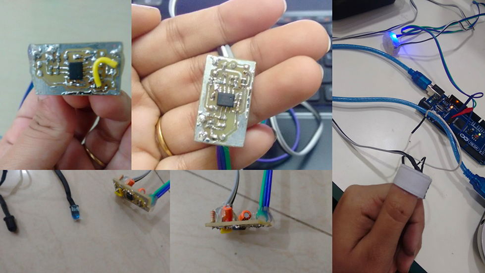
The sensor unit consists of an infrared light-emitting-diode (IR LED) and a photo diode, placed side by side. The fingertip is placed over the sensor assembly. The IR LED transmits an infrared light into the fingertip, a part of which is reflected back from the blood inside the finger arteries. The photo diode senses the portion of the light that is reflected back.
The intensity of reflected light depends upon the blood volume inside the fingertip. So, every time the heart beats the amount of reflected infrared light changes, which can be detected by the photo diode. With a high gain amplifier, this little alteration in the amplitude of the reflected light can be converted into a pulse.

Circuit Diagram
Explaining the Circuit

The reflected IR signal detected by the photo diode is fed to a signal conditioning circuit that filters the unwanted signals and boost the desired pulse signal.
The circuit diagram shows the IR LED (D1) and the photo diode (DR) along with the signal conditioning circuit made of two stage operational amplifiers configured as active low pass filters.
The cut-off frequencies of both the filters are set to about 2.5 Hz, and it can measure the pulse rate up to 2.5 * 60 = 150 bpm.
The gain of each filter is about 100, which gives the total 2-stage amplification of 10000. This is good enough to convert the weak
pulsating signal into a TTL pulse.
Note that at the input of each OpAmp filter stage, there is a 1 uF capacitor to block any DC component in the signal. At the output is
connected a LED that will blink with heart beat.
Testing on a Breadboard

The Schematic
MADE ON EAGLE

Printed Circuit Board Design
MADE ON EAGLE

Prototyping